Software runs its tests on
every commit. Hardware waits three weeks for the boards.Software tests every commit.
Hardware waits three weeks.CI for PCB designs: electrical simulation plus
firmware co-simulation, on every commit.
Hand it a board file. It works out the circuit the
copper implements, solves it, boots your firmware on an emulated MCU, and
fails a check while the design is still a file.
hauksbee run ESP32-EVB_Rev_L.kicad_sch --lint --plain1 serious
3 issues found, 1 serious.

1. [SERIOUS] A boot/strap pin on U3 and CR1 (net "GPIO0/XTAL1/CLKIN") will not be held at the level the chip needs when it powers up.
     Why it matters: Some chips read certain pins at the instant they reset to decide how to boot (which mode, where to load code from). If that pin is at the wrong level (or wobbling, e.g. a clock signal sits on it), the chip can boot into the wrong mode or fail to start.
     What to do:     Hold "GPIO0/XTAL1/CLKIN" firmly at the level the datasheet wants during reset, usually with a pull-up or pull-down resistor, and keep fast/active signals off that pin until after boot.
The Olimex ESP32-EVB puts the Ethernet PHY's free-running 50 MHz clock
on GPIO0, the ESP32's boot strapping pin, and the only pull-up that would
hold it is marked do-not-populate. Olimex fixed it in rev E. No firmware
runs here: this is the board's own copper. Verbatim; the run's two I2C
notes are not shown.
The full record.
Try it on a real board
Opens to four boards, spec presets, copper
layers and a live co-sim replay
Loading a recorded run
The real frontend, answering from runs the engine already made
on these boards. It loads when you reach it.
Measured against boards whose fixes are public
record: Raspberry Pi 4, MNT Reform, Olimex ESP32-EVB, SQFMI Watchy, ZSWatch
DevKit. Fault by fault, below.
FormatsKiCad, Eagle, Altium, or bare gerbers
Speedstatic checks in under a second; firmware co-sim in seconds
Localruns on your machine, and the board never leaves it
You do not need the schematic, or anyone's
permission: point it at the board file in the repository and read the
report.
One fault, in full
The most famous USB-C mistake ever shipped, re-derived from five parts
and a spec table.
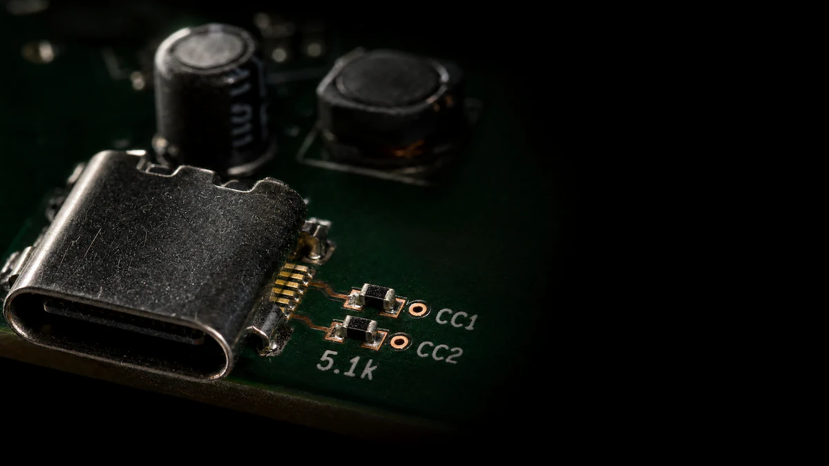
The Raspberry Pi 4 rev 1.0 and 1.1 tied both USB-C
configuration-channel pins to one shared 5.1 kilohm pulldown. Tens of
millions shipped before rev 1.2 gave each pin its own resistor.
Five parts and a spec table: the socket, the two
configuration-channel pins, and the pulldown each pin needs. Drawn
here with one resistor per pin, which is what rev 1.2 shipped. Rev 1.0
and 1.1 gave both pins a single shared one.
A generated illustration of a generic USB-C
power input, not a photograph of a Raspberry Pi.
Hauksbee holds no Raspberry Pi logic. It asserts the
spec's 80 microamp pullup on each CC pin, solves the network, and reads the
two voltages against the spec's own bands. Change the board and the
cable.
SinkAttached
VBUS applied
RaRd0.20 to 1.60 V
CC1CC2
0 V1.65 V, open
Solved configuration-channel voltages for the selected board and cable
Pin
Node
Solved
Reads as
CC1
80 µA into 5100 Ω
0.4080 V
Rd
CC2
not wired through
open
Open
A passive cable wires one CC line through, so the lone shared
resistor looks like an ordinary single Rd. This is why the fault hid:
the board charges from the charger most people tried first.
Thresholds are USB Type-C Specification Release 1.3, tables 4-20 to
4-28, and the solver agrees with hand arithmetic to better than 0.01%.
Both threshold
readings, with the arithmetic.
hauksbee run rpi4_usbc_as_designed.kicad_sch --usb-c --plainserious
USB-C PROBLEM: a standards-compliant charger will NOT power this board.

CC1 and CC2 are the SAME net, so a single shared pulldown terminates both. With an e-marked (USB-C-to-C) cable a compliant source classifies the port as AudioAccessory and withholds VBUS; the board will not charge from a modern cable (it would from a passive A-to-C). This is the Raspberry Pi 4 rev-1.0/1.1 fault.

  J1: CC1 Rd=5.1 kΩ, CC2 Rd=5.1 kΩ
  note: CC1 and CC2 resolve to a single shared net.

What to do: give CC1 and CC2 each their own 5.1 kΩ pulldown to GND (never share one, never tie them together), so a source sees a sink and applies VBUS.
Verbatim, in 0.06 s. The one human step was transcribing the
subcircuit from the published reduced schematic, because Raspberry Pi
releases no native CAD.
The full
derivation.
J1, DB9 socket
Every pad on it becomes a node in the netlist
before a single check runs.
U2, 74HC125
A part like this is bound to a device model,
and the report names the model it got.
P3, 40-pin socket
63 footprints on this board, and every one of
them was read out of the board file.
From copper to a red build, in three moves.
01
Read the copper
The design file is geometry, not a circuit. Hauksbee walks the
copper and hands back a netlist: on the SQFMI Watchy, 685 segments and
86 footprints, making 82 parts on 84 nets.
Every part is then bound to a device model, and the report says
which model it got and how confident that binding was, so a guessed
capacitor never passes as a datasheet part.
02
Say what has to hold
Three shapes cover most of it: a rail inside tolerance, a gate high
before a deadline, nothing past its rating. They compile to a TOML file
beside the board.
03
Fail on a file
Feed the ESP32-EVB's 3.3 V rail 18 volts and the stress monitor
names the part, not the symptom: U3, overvoltage, 18.000 V against a
3.600 V datasheet limit, 0.4 ms in. A scope on an assembled board says
the same a fab run later.
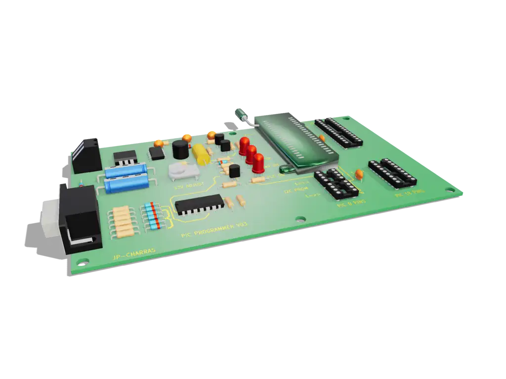
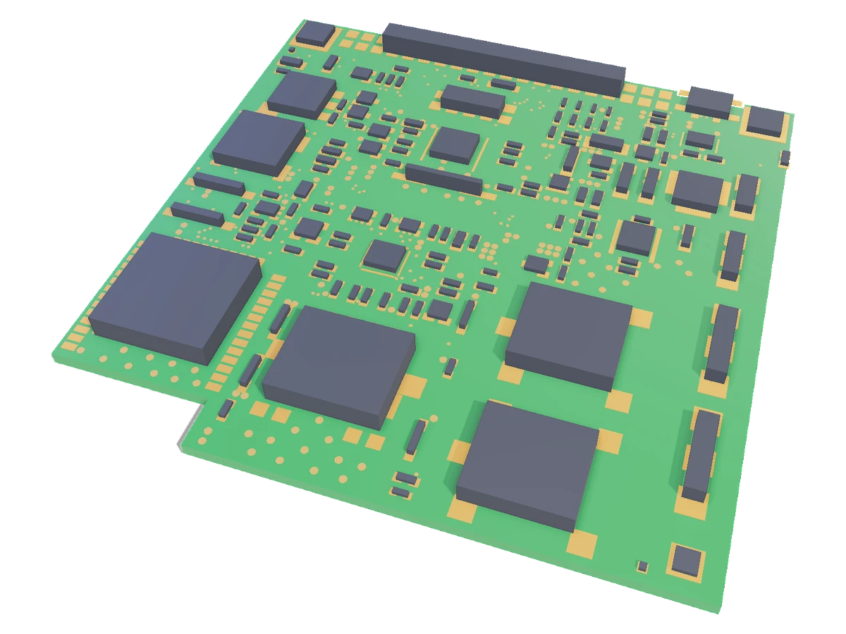
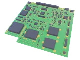
Shown alongside: the app's own 3D board view,
orbiting the PIC PROGRAMMER V03 example board, captured frame by frame
and scrubbed against this scroll. That model is the pre-exported one
that ships with the example boards; a board you drop in is built from
its own outline, pads and part bodies instead, so it looks plainer than
this.
Every fault on this page was
sitting in the copper the whole time.
The geometry was published, the
thresholds were in a spec, and nothing ran the arithmetic before the
boards were ordered. That is the entire gap Hauksbee closes: not better
judgement, just the check actually running while the design is still a
file.
Where it runs
A file beside the board, and a step in the
pipeline.
A TOML file you version with the layout, and a pinned
action, hook or Docker image to run it.
01
The spec lives beside the board
Board, firmware, how it is powered, and the assertions that must
hold. Versioned with the layout, reviewed in the same pull
request.
hauksbee-ci init my_board.kicad_pcb
scaffolds one from the board file. kind = "usb" models
the port's source impedance and current limit, so an inrush it could
never supply shows up as a sag.
02
Every push runs it
A GitHub Action, a pre-commit hook, or a Docker image. Exit codes
separate the four outcomes that matter: assertions held, an
assertion failed, the spec or board was wrong, or the analogue
result was not trustworthy enough to report.
hauksbee-ci: Watchy power-up
  board: boards/watchy.kicad_pcb
  seeds: 1

  [PASS] no stress faults raised
  [PASS] +3V3 in [3, 3.6] V after 50ms
        +3V3 after 50ms: min=3.300V (>= 3V), max=3.300V (<= 3.6V) [settled 3.300V]

2/2 assertions passed in 0.46s - GREEN
Some checks were not successful1 failing check
hauksbee-ci / boot-gate (pull_request)Failing after 4sDetails
Merging is blocked
[FAIL] GATE_CTRL driven to >= 3 V within 20 ms of reset
0/1 assertions passed in 0.02s - RED
A rendering of the check-run box, drawn in HTML rather
than photographed, so nothing here is a screenshot pretending to
be one. The two log lines are verbatim from the boot-gate run
printed further down this page; that run's exit 1 is what makes
the check red and blocks the merge.
JUnit XML comes out for the runner's own test
view, and the action
and images are on GitHub. No firmware in this spec; adding one and the
boot assertions puts the same board in the seconds.
The same file, composed rather than typed, and then run: the
panel on the left writes the TOML on the right, and every chip carries the
engine's own evidence line, down to D13: 9 toggles (need >= 5).
The board is the blinky example with demo.hex co-simulating,
and the result panel keeps the engine's caveat about asserting on a net an
ideal source feeds directly. A screenshot of that session in the app, so
what you are reading is the panel's own output rather than a mock of
it.
Tens of millions of boards shipped with that fault. The arithmetic
that catches it runs on the design file, before the first one is cut.
Evidence
Measured against boards whose fixes are public record.
The Watchy, the MNT Reform, the Olimex ESP32-EVB and
the ZSWatch DevKit fixed eight in-scope electrical faults across six
published revision pairs. That history is the ground truth, so the test is
exact, and every fault is one row below.
The Olimex ESP32-EVB rev D, drawn by Hauksbee from the
board file it was pointed at.
In-scope faults
8
Static checks
6
Firmware co-sim
1
Named misses
1
No check was widened to inflate that count: the
strap-pin lint fires on exactly one net across the corpus. Fault by fault,
with the netlist evidence:
the known-fault
validation.
All eight in-scope faults: the documented revision fix, and what happened when Hauksbee was pointed at both files
Board
The fault
Verdict
ZSWatch DevKit 1.2.0 to 1.2.1
Missing pull-ups on the RTC-side I2C bus
Flaggednetlist lint
ZSWatch DevKit 1.2.0 to 1.2.1
Sleep rail into an MCU pin through the nPM1300 hold pin
Flaggeddevice model
MNT Reform 2.5 to 3.0
Charger pulls 75 to 88 W from a 60 W brick
Flaggeddevice model, off the board's own programming resistors
MNT Reform 2.0 to 2.5
Gating charge current destabilises the same chip's converter
Flaggeddevice model
MNT Reform 2.0 to 2.5
Cell-balancing network leaks when a battery position is empty
Flaggeddevice model
Olimex ESP32-EVB D to E
A live 50 MHz Ethernet clock on GPIO0, a strapping pin
Flaggednetlist lint; rev E sequences the PHY's power rather than changing the net, so this two-sided proof is a constructed pair
Watchy v1.5 to v2.0
E-paper reset line with no pull-up: the display never sleeps
Flaggedfirmware co-sim on the emulated ESP32; a netlist alone cannot decide it
ZSWatch DevKit 1.1.0 to 1.2.0
Display-enable on a floating-capable GPIO, no pull-up
Missedits nRF5340 has no co-simulation backend yet
Three more documented fixes, ruled out of scope before the runs,
and why
The corpus turned up eleven documented
revision fixes. The method classified each one before opening a design
file, and RF, mechanical, firmware, EMC and transient thermal faults
are not Hauksbee's business, so three never went to a run. Counting
them would make the score eight of eleven; leaving them out silently
would make eight of eight look like the whole story.
Out of scope: documented fixes the corpus records and the scope rules exclude
Board
The fault
Verdict
MNT Reform all motherboard revisions
Standby drain: the LPC and keyboard MCU stay powered from an always-on 3V3 rail
Out of scopethe rail is that way by design and the fix that shipped was firmware deep-sleep, so there is no revision pair to be right about
Watchy v3
USB_DET held high about 500 ms after wake, so the watch wakes again immediately
Out of scopefirmware wake-source configuration against ESP32-S3 boot-pin behaviour, not a defect in the copper
Olimex ESP32-EVB C to C1, H1 to I
Reset RC values tuned across revisions for start-up reliability
Out of scopea timing margin rather than a connectivity or rating defect; deciding it needs a calibrated reset-threshold and brown-out model Hauksbee does not have
The miss, stated plainly
A control input on a floating-capable pin with no pull is not
separable from a harmless twin on a static netlist: the same shape appears
on boards that work fine. Running the firmware makes it decidable, which
is how the Watchy row closed. The nRF5340 has no backend yet.
What the clean sweep says
Pointed at two dozen well-known open boards across five rounds,
Hauksbee reported no unreported defect and zero false positives. These are
shipped, reviewed, working boards, so clean is the right verdict. The
yield of that sweep was about ten bugs in Hauksbee itself, each chased to
ground and fixed.
One false positive costs more than one miss
A tool that cries wolf gets switched off, and a switched-off tool
catches nothing. So a misfiring check is overruled one finding at a time,
by a waiver with a required reason and expiry, printed rather than hidden.
The rest of the apparatus.
The stress monitor names the part and the rating, not the
symptom: U1 overvoltage, 18.000 V against a 6.000 V
limit, 3.1004 s in. The rail was turned up to 18 V in the app;
nothing else about the board changed. Screenshotted from the app, not
drawn.
A probe on a co-simulated net, which is the measurement the
firmware rows rest on: D13 squares between 0 V and
4.601 V as demo.hex blinks it, and
ADC0 holds 2.500 V off the divider.
Screenshotted from the app, not drawn.
hauksbee-ci run boot_gate_fail.tomlexit 1
hauksbee-ci: boot_coverage: MOSFET gate left floating (FAIL)
  board: boards/boot_gate.kicad_pcb
  seeds: 1

  [FAIL] GATE_CTRL driven to >= 3 V within 20 ms of reset
        control net 'GATE_CTRL' was never driven to >= 3 V (firmware left it Hi-Z / undefined through the whole run); observed range [-0.000, -0.000] V

0/1 assertions passed in 0.02s - RED
Why the co-simulated row is a measurement and not a
formality: the same board and assertion go red on firmware that leaves
the net alone. 0.02 s, boot-gate example, AVR co-sim.
What is covered, by MCU family
Static checks and the analogue solve read the board, so they run
whatever the MCU is, or if there is none.
Co-sim proven end to end on AVR, STM32 F103 and ESP32 / ESP32-C3:
boot, GPIO and UART.
Boot-only on nRF52840, FE310 and ESP32-S3: the machine boots, the
rest is unproven.
Converter injection is exact on AVR alone; Renode platforms refuse
one out loud rather than guessing.
The full matrix, cell by cell, is on the
limitations page,
with the AC sweep and thermal caveats beside it.
3,442components on the largest board it solves, decomposed at device bounds
0.46 sthe 82-part Watchy through the CI gate, static checks only
better than 0.01%disagreement between the solved CC voltages and hand arithmetic
zerofalse positives, two dozen shipped open boards, five sweep rounds
macOS and Linux today, with a Docker image if you
would rather install nothing; Windows is being evaluated, not promised.
v0.1.0-beta.3, Apache-2.0 source
Install it and point it at a board.
One line on macOS or Linux. The macOS build is signed and notarised;
double-clicking it opens a drop zone in your browser, where you drop a
board, read the report, zoom the copper until part labels appear, and take
the spec file with you.
Read
the script before you run it. It downloads the release and its
published .sha256, verifies the checksum, and refuses to
install anything if they disagree or if neither
shasum nor sha256sum is available to check.